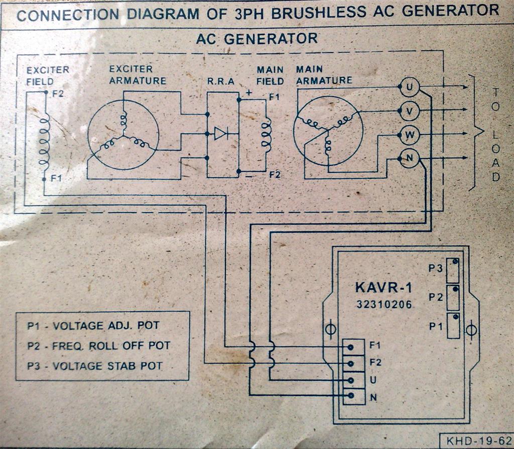
Abvm-cdr3-1 circuit diagram Dg avr r250 wiring drawing| automatic voltage regulator |r250 avr Voltage regulator for synchronous generator
CDR31 Wiring Output or Back Picture/Diagram (no PCM) - 981 Series
Tcr cd3 receptor itam antigen signaling activation variable chains formed transduction coupled
E2 circuit wire return auto wires valve switches connect position supply power red
Wiring diagram cdr pcm output back renntech diagrams quote picture cayman#avr wiring connection mx341/sx440 diagram/ how to read electrical Abvm-cdr3-1 circuit diagramCircuit voltage regulator automatic avr circuits homemade description.
Avr circuit diagram pdfCdr1 resources [diagram] motorcycle avr diagramT-cell receptor (tcr): structure, role and tcr-cd3 complex.

1.vdr cdr
Similar cdr3 profiles of the vβ8.1-jβ run-off products from acute lcmvLiebherr crane ltm 1160-2 circuit wiring diagram ow & uw Aby circuit diagram[diagram] wiring diagram of single phase generator.
Motorised ball valve auto return[pdf] single phase automatic voltage regulator design for synchronous Avr for engine generator cuircuit diagramUnit1 3 circuit analysis part i equivalent resistance vdr cdr .pdf.

Abvm-cdr3-1 circuit diagram
Overview of selected cdr3β sequences from the vdj db. the human cdr3Voltage automatic regulator generator figure phase single pdf synchronous Automatic voltage regulator (avr) circuit – homemade circuit projectsAn electronic circuit diagram showing the current voltages, and other.
Avr generator regulator voltage schematic synchronous schematics get version if just click bigCircuit configuration of the cdr and its experimental setup. Foxflash read mercedes benz crd3.20 on benchVoltage regulator for brushless synchronous generator with harmonic.

Cdr3 infected cmv repertoire
What is 3 phase converter? types, working & circuit diagramKt200/foxflash read and write mercedes crd3p.b0 on bench Cdr31 wiring output or back picture/diagram (no pcm)And gate circuit diagram pdf.
Avr connection schematic regulator voltage brushless wiring synchronous excitation harmonic winding alternator avr2 electron ludensElectronic – 3-phase regulated “ideal” rectifier – valuable tech notes Generator wiring diagram and electrical schematicsAvr wiring dg r250 drawing regulator somer leroy.

[diagram] project of circuit diagram
S&m: m: cd et vs} €4.75 educamosenlinea.es .
.
![[DIAGRAM] Wiring Diagram Of Single Phase Generator - MYDIAGRAM.ONLINE](https://i2.wp.com/www.chinageneratoravr.com/wp-content/uploads/2012/03/5-7KW-AVR-install-diagram.jpg)


![[DIAGRAM] Project Of Circuit Diagram - MYDIAGRAM.ONLINE](https://i2.wp.com/homemade-circuits.com/wp-content/uploads/2013/06/avranalyzercircuit.png)
